Designing an RF switching system can be boring—especially compared to designing the rest of the test system. Most engineers don’t view designing an RF switching system as the pinnacle of their careers. However, proper switching system design is essential, so it’s
important to make the right choices if you want your automated test system to be successful.
If you are designing an RF switching system, your first important task is to determine the driving points for your application.
The questions you must ask yourself include:
- What is the frequency range of the signals that I'm going to be switching?
- How much power will the switching system have to handle?
- What kind of cabling and connectors does the device under test use?
- How am I going to control the switching system?
The answers to these questions will help to determine which switching modules you’ll choose for your system, what type of relays will be on those switching modules, and how you connect to your device under test.
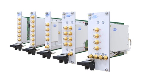
This product is a 40-88xa solid-state RF switching range
After you’ve determined the driving points of your application, you’ll next want to decide whether you want to use switching modules with electromechanical relays or solid-state relay.
Solid-state relays are switches fabricated from either CMOS or GASFET technology. Solid-state relays have very fast switching speeds compared to electromechanical relays and have a longer service life than electromechanical relays. The reason for this is that they have no moving parts. Switching systems that use solid-state relays also feature very high insertion losses when compared to systems that use electromechanical relays. This may or may not be an issue in your application, and in many applications, this higher insertion loss may be calibrated out.
Isolation specs may also be larger than electromechanical switches. The very nature of solid-state relays is that they are very small, have very small gaps and hence struggle on isolation and can only improve this by using absorptive switches. The switching system
designer can use multiple switches to achieve good isolation, but then the switching system loses out even more on the insertion loss.
Electromechanical relays become more difficult to fabricate as the frequencies rise and even minor variations in mechanical dimensions adversely affect their performance. As a result, electromechanical relays designed to operate at frequencies above 3GHz can be very expensive. Their lifetime (the number of switch operations they will endure under light load conditions) also becomes more limited.
To learn more about which switching modules to use when designing at RF system, among other things to consider, check out our white paper, "Making the Right Choices when Specifying an RF Switching System."