
 When I was in high school, a long, long, LONG time ago, I was helping a buddy rebuild a 1955 Chevy Belair (the Belair was not an antique then. In my senior year of high school, it was only 15 years old 😊). Anyway, my friend had already rebuilt the engine, and we installed it and the transmission pretty quickly. But something was wrong. It was very hard to start, and we kept burning up voltage regulators. Both of us were scratching our heads when one afternoon, as I was adjusting the carburetor, I burned myself! The weird thing was that I burned myself on the choke cable (For those of my readers who did not grow up in the “Dark Ages” of the 1950s and 60s, the choke cable was a thin cable that adjusted the air-to-fuel ratio manually. Old school). This was not supposed to happen! Then we realized our error. The engine and transmission are attached to rubber mounts to reduce vibration, electrically isolating the drive train from the return connection to the battery. We forgot to ground the engine to the vehicle! With no ground strap, the choke cable was the return for the battery. The diameter of the choke cable was such that it was in effect a resistor and the voltage drop across it (cars used 6-volt batteries then) meant not enough power to adequately engage the starter motor, but enough IR drop on the choke cable to burn my arm.
I bring up this story not to be nostalgic but the lesson applies to electronic test. Wiring in your functional test system needs to be the appropriate gauge and insulation rating for the voltage and current to be switched. Too high a gauge can have unacceptable IR losses and generate heat in the cable. Inadequate insulation means a potential shock hazard for the operator and other test issues. Like my experience with the choke cable, operators can feel the heat, which is not correct. So, referring to my first post, "Electronic Testing 101: What to Ask when Reviewing Test Specs or Reqs," know what you are switching before you specify cables.
Download or request a hard copy of our FREE SwitchMate eBook for an overview of switching for automated test systems.
What is less obvious is how a multi-wire cable impacts the performance of a cable assembly under load. For example, how many wires can carry full rated current at the same time without an excessive temperature rise in the cable? Your cable vendor of choice should be able to provide these key specifications. Here is a typical specification chart for a 50-wire cable:
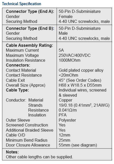
Current Ratings - This is typically for a single wire and is also limited by the connector rating. As more wires are loaded to their maximum current rating, cable temperatures will rise. At some stage, a maximum load current for the entire cable/connector assembly should be specified.
Voltage Rating - This is limited by the connector used and the construction of the cable (insulation materials, clearance distances).
Temperature Rating - The datasheet will include information about the recommended maximum working temperature for various parts of the cable assembly. For cables based on the high-temperature material PFA, the copper should not get to more than 260 C. Cables using polyester outer materials should be limited to a surface temperature of 100 C. However, how this translates into a load rating is complicated because of the varying conditions that users might have, including the ambient operating temperature of the cable assembly.
Thermal Time Constant - The critical parts of the cable assembly will include a thermal time constant that can be used to estimate the ability of a cable to withstand a short-term higher load than the static conditions would suggest.
Try our FREE cable design tool to create a custom cable assembly
In my next post, I will talk more about connectors and the problem of lengthy cables.
For more information cables, watch the webinar "Simplifying Test Interconnect with Pickering's Cable Design Tool" and check out our Connectivity webpage.

<< View the previous blog post in this series, "Electronic Testing 101: The Different Types of Relays and their Specs"
View the next blog post in this series, "Electronic Testing 101: Cables and Connectors" >>