Within small switching system configurations or when utilizing just single switch modules, the user typically applies device drivers with the provided API to control the relays. Simple CLOSE and OPEN commands with additional parameters like module number and channel number control the required relays.
The user must always take care in order to avoid shorts or malfunctions even when performing simple switching tasks. If there are many relays involved, the risk of error increases significantly.
The example below of a 4-wire resistance measurement where a Digital Multimeter (DMM) and the Device-Under-Test (DUT) are connected to the matrix X-axis; turning a simple switching setup into something more complex.
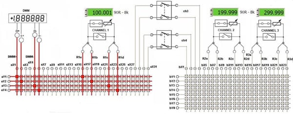
For the correct measurement, all four signal paths between DMM and DUT must be properly set, meaning all crosspoints on all four Y-axis’ must be closed at the correct X position. If only one is wrong, it will end up in erroneous measurements or possible shorts to adjacent DUT terminals. For another example, an additional 4-wire resistance measurement takes place on the second matrix. Two 2-pole relays are cascading both matrices by interconnecting Y-bus 1 to 4. Now, even more relays distributed on three different modules have to be programmed properly to achieve a correct measurement.
It is obvious that switching system complexity increases when multiple modules configured and interconnected with each other are carrying signals routed throughout the system. For this reason, switching and routing software, like our Switch Path Manager, takes its role to manage any configuration complexity, yet remains easy to use and always takes safety aspects into account.
Switch Path Manager virtually describes any switching architecture and processes all stored project data for switching and routing at runtime. A multivendor and platform independent switch module library provides the models that are added to the project. In addition, the physical interconnections as well as the endpoints have to be defined. Endpoints are the boundary of the system where measurement and stimuli equipment and all the UUT access points are connected. By calling Point-to-Point or Point-to-Multipoint functions, the routing is processed, and the required relays are controlled to establish a signal path between these endpoints. The router will never interfere with existing routes and will find an alternate bypass or will terminate with an error message if not successful.
Continuing the first example and extending it to a 4-wire resistance measurement DMM to R2 (Channel 2) there are four routes to be established and therefore four CONNECT functions to be called. When using the device driver, 18 CLOSE commands have to be sent to achieve the same setup. Besides the increasing the number of commands, good knowledge of the system is required to understand which crosspoints have to be used.
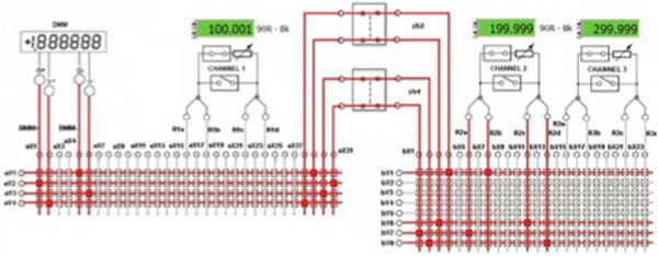
Switch Path Manager with Auto-Routing
- Connect Endpoints (DMM+, R2a) - to disconnect: Disconnect Endpoints (DMM+, R2a), etc.
- Connect Endpoints (s+, R2b)
- Connect Endpoints (DMM-, R2c)
- Connect Endpoints (s-, R2d)
Classic Device Driver
- Close Crosspoints (module1, y1, x1) - to disconnect: Open Crosspoints (module1, y1, x1), etc.
- Close Crosspoints (module1, y2, x2)
- Close Crosspoints (module1, y3, x5)
- Close Crosspoints (module1, y4, x6)
- Close Crosspoints (module1, y1, x29)
- Close Crosspoints (module1, y2, x31)
- Close Crosspoints (module1, y3, x30)
- Close Crosspoints (module1, y4, x28)
- Close Channel(module2, ch3) - to open: Open Channel (module2, ch3) , etc.
- Close Channel(module2, ch4)
- Close Crosspoints (module3, y1, x4)
- Close Crosspoints (module3, y6, x3)
- Close Crosspoints (module3, y7, x1)
- Close Crosspoints (module3, y8, x2)
- Close Crosspoints (module3, y1, x14)
- Close Crosspoints (module3, y6, x6)
- Close Crosspoints (module3, y7, x8)
- Close Crosspoints (module3, y8, x12)
If frequently recurring, routes are required it might be more efficient to create fixed routes instead of calling Endpoint-to-Endpoint connections. Those routes can be grouped together to make connecting and disconnecting even simpler. Each separate route holds an attribute called Auto-Route or Static-Route. Thus determining in advance whether a route selects an independent path based on the current switch status or a static one, which might fail if an existing route is blocking the way.
For the R2 4-wire measurement four single routes (R2_DMM-, R2_DMM+, R2_DMMs+, R2_DMMs-) are grouped (GRP_DMM_R2) and switched by single Connect Route Group commands:
- ConnectRouteGroup (GRP_DMM_R2) – to disconnect: DisconnectRouteGroup(GRP_DMM_R2)
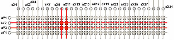
Switch Path Manager handles individual relay control as well: a relay group, which is a group of one or more relays, is called by function:
- ConnectRelayGroup (RELAYGRP) – to disconnect: DisconnectRelayGroup(RELAYGRP)
For example, relay group RELAYGRP contains the relay channel information of crosspoints Y2/X10, Y2/X11, Y3/X10, Y3/X11.
Short Circuit Detection (SCD)
A very important aspect, when applying routing software, is short circuit detection. If not handled correctly, routing might create shorts in a switching system. In the configuration below, there are two switching systems interconnected via a normally closed relay. Now, with an existing route established between A and B, a second route from C to D would cause an unwanted short of the two systems. The Switch Path Manager short circuit detection (SCD) prevents this condition, returns an error message and will not switch this second route.
Another more obvious example illustrates the short circuit detection when using multi-pole relays: Two matrices are interconnected on their Y1 and Y2 lines via a 2-pole relay. The blue and green routes have already been switched. Another signal path from X1 left side and X3 right side would allow a route over one pole of the 2-pole relay. However, Switch Path Manager prevents the closing; as on the first pole the green and the blue existing routes would then inadvertently be shorted.
Signal Isolation
If the switching system’s signal leads are not isolated, and therefore used for routing, it can lead to unintended connections and therefore to short circuits. The two block diagrams below illustrate this within the following task:establish two independent connections Y1-Y4 and Y2-Y3.
The router searches for the best-unused path and switches the crosspoints regardless of what is connected. Picture 1 below shows an unwanted connection to the DMM+ and s+ leads, this happens because the router does not know which signals are applied to given nodes. Picture 2 below shows the routes on absolute free paths without any connections to the outside world; this happens because X1, X2, X5 and X6 (used for the DMM) are defined as “isolated” in the system configuration.

Picture 1 Picture 2
Conclusion

For smooth and easy implementation of switching applications with minimal coding, switching and routing software like Switch Path Manager is unbeatable compared to low-level programming. A good and accurate setup helps minimize the risk of short circuit switching.
The performance speed of routing software should be considered separately. Such systems will always be slower compared to optimized direct programming; this is especially true when used in small switching configurations with one or very few switch modules. However, these delays are small, in the order of milliseconds.
Our Switch Path Manager supports our switching modules and the interconnection between these products; third party products can be supported upon request. Please contact us with any questions.