In the world of test and measurement, precision, efficiency, and adaptability are essential to success. MEMS, which stands for Microelectromechanical Systems, is a microscopic switching technology that is revolutionizing the field, especially in RF & microwave switching. MEMS devices incorporate both electronic and mechanical moving parts and consist of components ranging from 1 to 100 micrometers.
First presented to DARPA (Defense Advanced Research Projects Agency) by the University of Utah in 1968, MEMS devices have found their way into a variety of applications, including inkjet printers, accelerometers in modern cars for airbag deployment, electronic stability control gyroscopes for drones and optical switches but until now could only carry small signals, making them unsuitable for electrical test.
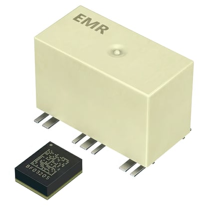
In terms of electro-mechanical switches, MEMS switches are fabricated on silicon substrates where a three-dimensional structure is micro-machined (using semiconductor processing techniques) to create relay switch contacts. The contacts can then be energized using either a magnetic or electrostatic field. Like Reed Relays, MEMS can be fabricated so the switch contacts are hermetically sealed (either in a ceramic package or at a silicon level), and this generally leads to consistent switching characteristics at low signal levels.

Much has been written over the years about the promise of MEMS technology for RF switching as an alternative to the commonly used Electromechanical Relay (EMR) and Solid-State (SS) switching solutions. However, technical challenges tempered the potential it could practically deliver. Many of these hurdles have now been cleared, and commercially viable RF switching solutions are now gaining traction for Test & Measurement (T&M) applications where fast switching speed and a very long operational life are necessary, alongside consistent, low-loss RF performance.
Advantages of MEMS Switching Technology
- Performance and Futureproofing: Solid-state switches have a virtually infinite life but high insertion loss and AC-coupled signal paths, making them unsuitable for many RF applications. On the other hand, electromechanical relays (EMR) exhibit excellent RF characteristics from DC to around 3 GHz with low insertion loss. Still, their typical life expectancy of 10 million operations limits their use to relatively low-volume testing environments. The appeal of MEMS switches is that they have the superior RF performance of an EMR coupled with the long life of an SS switch. MEMS switches can also operate to higher frequencies than EMRs, making them a future-proof choice and allowing you to test more advanced products without upgrades.
- Life Expectancy: MEMS switches are designed to be incredibly long-lasting, with a life expectancy far exceeding traditional EMR-based solutions. This is crucial, for example, for high-volume semiconductor customers with 24/7 test operations, where frequent system maintenance can be a significant concern. It also means that MEMS switches are ideal for HALT (Highly Accelerated Life Test) and HASS (Highly Accelerated Stress Screening) applications, where test procedures can take weeks to complete. MEMS switches offer over 300x operational life and 60x test system throughput compared to EMR-based solutions.
- Reduced Cost to Test: Thanks to their longevity and speed, MEMS switches can significantly reduce the cost of testing vs EMR solutions. You'll spend less on system maintenance and be able to increase your testing capacity without a corresponding increase in costs.
- Low Insertion Loss: To preserve the integrity of signals during testing, MEMS switches offer low insertion loss, comparable to EMR and significantly better than SS switches.
- Application Diversity: MEMS RF switches can handle 25 W above 10 MHz compared to 10 W for EMRs. This high-power handling coupled with the fast switching means they are potentially more suitable for demanding applications than EMRs.
Disadvantages of MEMS Switching Technology
While MEMS technology offers numerous advantages, it's important to be aware of its limitations:
- Hot Switching: MEMS switches do not handle hot switching well and should always be cold switched, i.e., operated when passing no signal. Hot switching, where a signal is connected while the switch is operated, can cause arcing, which can damage the extremely small MEMS contacts. Factors such as capacitor discharge and cabling must also be considered when using MEMS technology to avoid accidental hot-switching events.
- Factors Influencing Choice: The choice between MEMS and other switching technologies depends on the number of operations dictated by test requirements, the need for fast switching, and power and insertion loss requirements.
MEMS vs. EMR and Solid State Switching Solutions
|
|
MEMS |
EMR |
Solid State |
|
Frequency Range |
DC to 4 GHz (usable to 5 GHz) |
DC to 3 GHz |
10 MHz to 8 GHz |
|
Insertion Loss |
<1.4 dB to 4 GHz |
<1.0 dB to 3 GHz |
<6.0 dB to 8 GHz |
|
VSWR |
<1.5:1 to 4 GHz |
<1.4:1 to 3 GHz |
<1.95:1 to 8 GHz |
|
Max RF Power |
25 W to 4 GHz |
10 W at 3 GHz |
4 W at 8 GHz |
|
Operating Time |
50 microseconds |
3 milliseconds |
50 microseconds |
|
Life Expectancy |
3 billion operations |
10 million operations |
Indefinite |
|
Hot Switching |
NO |
Better tolerance |
Some tolerance |
|
Price per channel normalized to EMR |
1.3 |
1 |
1.9 |
*Figures are for typical Pickering PXI switches for each technology.
Pickering Interfaces’ Partnership with Menlo Micro
To meet the increased requirements from our high-volume semiconductor customers, we recently joined forces with Menlo Microsystems—a technology company that specializes in developing advanced MEMS technology for a variety of applications—to help advance our PXI & PXIe MEMS-based RF multiplexer product line. Menlo Micro has been at the forefront of perfecting electrical switching in a MEMS environment, making it one of the first companies to achieve this feat and a natural fit with our mission at Pickering to meet the demand from our high-volume semiconductor customers. This partnership has led to the creation of our MEMS product family, which offers several advantages vital to our customers’ success. Unlike traditional electro-mechanical relays (EMRs), the MEMS-based modules we developed using Menlo Micro’s Ideal Switch® offer excellent RF characteristics up to 4 GHz and an operational life exceeding 3 billion operations, a significant improvement over the maximum 10 million operations typically offered by EMR-based solutions.
Menlo Micro Case Study: When cycles matter: Upgrade existing EMR PXI RF multiplexer solution
![]()
Key Specifications for 40/42-878 PXI & PXIe MEMS-based RF Multiplexers
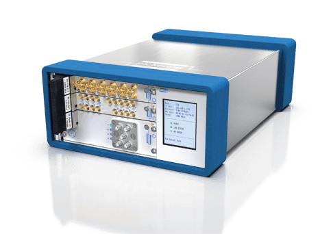
- Available as PXI or PXIe modules
- 4 GHz RF Multiplexer
- Maximum RF Power up to 25 W
- Operational life of over 3 billion operations
- Available in single, dual, and quad versions
- Choice of SMB or MCX connector versions
- Very low insertion loss
- Fast operating time (50 microseconds)
- Drivers provided for Windows and Linux, with support for real-time systems
- PXI versions supported by PXI or LXI chassis
Check out our MEMS based RF Multiplexer
Conclusion:
MEMS switching technology is a game-changer for high-volume RF & microwave customers. By offering speed, durability, reduced testing costs, and low insertion loss, MEMS switches have become an invaluable asset in the field. Understanding their limitations and benefits is crucial for selecting the right technology to meet your testing requirements while achieving the perfect balance of precision and efficiency.