A goal of any manufacturing organization is to maximize the time that their test systems are operational. A test system that is down due to maintenance issues costs a company significant dollars in unrealized revenue. Switching systems, and in particular, matrices, are central to most automated test systems and rely on relays as the switching element. Relays are mechanical in nature, and as such, may fail over time for various reasons. This white paper explores these issues and discusses methodologies that can help shorten repair cycle time, in turn, sustaining and maximizing system uptime.
Matrices allow for very flexible connection strategies between a single core set of test equipment and one or more DUTs (Devices Under Test). This approach saves the cost of duplicating test equipment; however, it also means that the switching matrix is placed in a central, potentially vulnerable position, where it may be subjected to abuse or accidents during use due to programming errors in development, wiring errors or unexpected DUT faults. Typical repair cycles can take up to 2- 4 weeks and can be extended when faults cannot be reproduced at the OEM.
The main factors that affect test system matrix reliability are the choice of relay used for the signal switching, and the conditions under which the relays must operate. The relays used in most matrices are mechanical devices whose lifetime is determined by the quality of their construction and moving parts, and the contact materials. A faulty relay can bring a production line to a halt; therefore, quick identification of the fault and subsequent repair is crucial in getting the system quickly back online, enabling product shipping to resume. High-quality EMRs (electro-mechanical relays) can have lifetimes in the order of 100 million operations under light load conditions. Still, instrument-grade reed relays have lifetimes in excess of one billion operations, and it is for this reason, as well as their smaller size, that reed relays are generally preferred.
Factors That Influence Relay Lifetimes
The conditions under which relays are operated impact the integrity of the contact materials. While in most cases it is best to ‘cold switch’ a signal – i.e., perform the switching operation without any applied current or voltage stimulus – that’s not always possible. But it must be noted that ‘hot switching’ – opening or closing a relay while it is carrying a signal – reduces relay life. Relays that hot switch signals run hotter than relays that cold switch and their contacts will erode much faster. Both of these factors – temperature and contact damage - will cause the relay to fail sooner. In general, vendors life-test relays with resistive sources and loads. In the real world, however, loads can be both inductive and capacitive, and these loads can shorten relay life to a greater extent than simple resistive loads.
It is not always obvious how much voltage or current is being hot switched by a relay. For example, if a relay is connecting a low impedance source to a high impedance load, it could be expected that the switched current will be relatively low. However, if the cabling or load has significant parasitic capacitance, there may be a high surge current through the relay when it closes as the source charges the effective capacitor.
A relay may also experience a high surge current when it connects a source to a capacitive load that is carrying a charge from a previous state. This might occur, for example, when a switching system reverses the polarity on a DUT, or if an earlier operation has left a charge on a high impedance load.
Switching systems are also typically capacitive at their terminals. If a switching matrix has a large number of closures on a single Y-axis to X connections, the resulting capacitance can create an extra load that can shorten relay life when hot switching.
Resistance in the cable wiring and the PCB tracks can help reduce the surge currents and therefore increase relay life, but this effect declines rapidly as the signal voltage increases.
High current or high-power inrushes are the most damaging and most frequent cause of contact damage. As well as inrushes due to charging capacitive loads, discharging capacitors can be an even more significant issue as the current is often only limited by the resistance of the reed switch and PCB tracks. Even capacitors charged to quite low voltages can cause current inrushes of tens of amps, and although they may be for microseconds only, they can cause damage to small reed switches.
The most common failure mechanisms for switching system relays used to hot switch signals are:
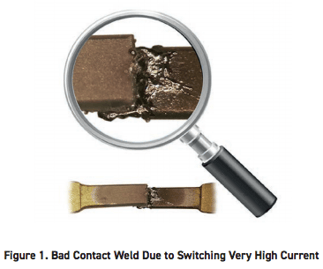
- Welded contacts - usually caused by high inrush currents as the contacts are closed, creating molten or soft metal in the contact area - Figure 1.
- Contacts having variable or intermittent contact resistance. This occurs particularly at low current levels because of the erosion of the contact materials. It may also be that the relay is reaching end of life.
- Failure to close – caused by severe erosion of the contacts or the build-up of debris on the contacts (more an issue with EMRs as their contacts are exposed to air; reed relays have hermetically sealed contacts).
A fuller discussion of factors that influence the lifetime of relays can be found in our white paper entitled ‘Avoiding failure modes in switch systems for test.’
Often, failures in test systems are caused by accident. For example, cabling and software errors can cause parts of the system to be connected that were never intended to be, resulting in shorts on power supplies or turning hot switch events into capacitive loads. The relay may withstand these accidents, but it could suffer partial damage to its contacts, which will shorten its operational life as the system is used and ages. Even when the system is operating correctly, an attempt to test a faulty DUT can force operation beyond the relay specification, stressing the switching system.
Fault Diagnostics
Historically, due to demands from customers (usually military or aerospace), platforms such as VXI have offered a self-test facility for the relays. However, the extent of test coverage provided could be patchy. Sometimes only the control system was tested and not the relay contacts (the most likely part to fail); other practices tested the relay contacts through hardware internal to the switch module, but it could not test the integrity of the connector. Products based on smaller footprint platforms, such as PXI, did not initially provide self-test. This gave rise to perhaps one of the most misguided approaches to managing the issue – ‘relay counting’. Here, the software counts how many times a relay has been operated so that the relay can be replaced when the number of operations reaches a given threshold. This method is deeply flawed for several reasons:
- Relay life changes by three orders of magnitude according to the load present. The software has little or more commonly no knowledge of the load. It is merely a counting system.
- It takes no account of the accidents that happen in systems, such as UUT failures, that shorten relay life.
- Relays are subject to significant variations in lifetime by batch.
The consequence of this is that real switching systems can have a much shorter or much longer life than a relay counting system will indicate.
Diagnostic Test Self Test Tools
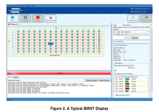
The good news is that the status of self-test is changing. Pickering now provides PXI matrix solutions, which include a built-in self-test facility called BIRST™ (Built-In Relay Self-Test), which addresses the shortcomings of the older self-test systems and the relay counting methods. BIRST is implemented as a very compact hardware addition to the PXI modules; the source/measure hardware is on-board and measurements are made through the matrix. It works in conjunction with a dedicated software application to electrically explore the matrix, measuring the resistance of each signal path with repeatability measured in a few milliohms. The user simply needs to disconnect the PXI module from the test system and then run the BIRST program. The test process is fast, each relay requiring just a few 10s of milliseconds to test fully. The software then displays the test results as a graphical representation of the matrix, highlighting any relays that are faulty and allowing the user to identify the physical position of each faulty device quickly. Every relay is checked; welded closed and stuck open relays are quickly identified.
BIRST only identifies those relays which need attention for maintenance and avoids unnecessary disturbance and system downtime. The tool can identify relays with higher than expected path resistance, allowing users to change those relays before they fail. Through-hole relays are extensively used on Pickering’s switch matrix modules, allowing the user to self service the module with commonly available tools and get it back into service quickly. We encourage this practice: warranties are unaffected, and we even supplies spare relays on each switch module for the purpose
Our eBIRST external diagnostic test tools work similarly to BIRST but require an external test tool to be connected to the switch module under test. The relay testing source/measure hardware is contained within the tool, and an eBIRST software application exercises both the module and the connected tool and returns the relay test results and analysis.
While BIRST identifies faults within the matrix, it cannot verify the switch module’s front panel connector. So if a connector is damaged in any way, BIRST will not help. This is a key advantage that eBIRST brings: it allows the user to analyze the switching system right out to the external interface. The eBIRST test hardware can be connected directly to every individual relay on the switch module via the external connector, and this results in superior fault resolution compared to the BIRST tool, which tests relays using discrete matrix paths consisting of multiple switches. Another significant advantage is that eBIRST is available for any configuration of the switch module, not just matrices.
Like BIRST, eBIRST enables faulty relays to be identified so they can be replaced by the user on-site with minimal downtime. As with BIRST, we encourage this practice, and again, the warranty is unaffected.
The eBIRST tools are self-contained; only a USB2 port on a PC running Windows and the supplied application program are additionally required. The program uses a Test Definition File created for each switching module that defines how to test it. This enables users to test any of our switching systems that use mechanical relays with precious metal contacts (typically contacts with a rating of 2A or less) and also those incorporating solid-state relays. DC coupled RF systems using SMB connectors are also supported using test adapters. Each tool is generic—it will support DC-coupled switching systems that use multi-pin connectors on our PXI, PCI and LXI controlled switching systems. eBIRST also supports all-new generations of our BRIC matrix solutions, which now feature cross-point counts of over 9000 in a compact PXI module.
Signal Routing Software
Once the user has run BIRST or eBIRST diagnostic test tools and has discovered a faulty relay in a matrix, they may find that testing is still halted as they do not have a spare matrix (or relay) in stock. However, by using our Switch Path Manager (SPM) software, there may be a way to keep the tester functioning until a replacement is available.
Switch Path Manager simplifies signal routing through switching systems and speeds up the development of switching system software. Switch Path Manager supports our switching modules and the interconnection between them. Once a switching system model has been created, signal routing can be performed simply by defining the endpoints that are required to be connected—the ability to automate signal routing results in effective and easy switching system management.
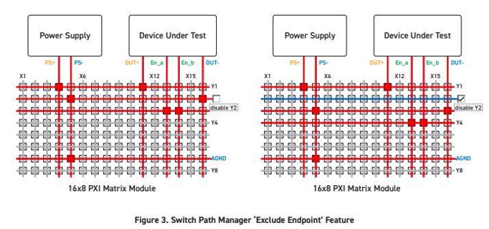
In the event described above where a faulty matrix relay is discovered, but no replacement is immediately available, and repair by the user is also not an option, the operator can use the Exclude Endpoint feature within SPM to instruct the router not to use that path in its calculations. Figure 3 shows a matrix connecting a power supply to a DUT. The left-hand side shows the relay closures necessary to make the connections. However, if a relay fails along the Y2 axis, in SPM, a single command can be used to set up the router to avoid using Y2. This is shown on the right-hand side of the figure where we see that the switch path that originally used Y2 now uses Y3. Once the matrix has been repaired or replaced, the test engineer can remove the exclusion, and the program will run as before.
A thorough understanding of the factors that adversely affect the life of mechanical relays – the critical component in a switching matrix – will enable preventative maintenance based on proper operating procedures. This will reduce test system downtime and improve productivity. If a component does fail, new test procedures will allow the rapid detection of the fault, and expedite its repair, or provide an effective means to work around the problem.
If you have questions on your PXI test system maintenance - please feel free to contact us or visit our Support Knowledgebase for answers.