OOPS, I left out one configuration in my last post:
Transfer Switch – Essentially, a Transfer switch is a double-pole/double-throw (DPDT) design for RF and Microwave applications. They have four ports with two possible switch states and have the capability to switch a load between two sources. Applications are mainly in the microwave region. However, there are many uses in the RF spectrum where extremely low insertion loss and ultra-high isolation are critical. They may also be used for lower frequency RF applications where power handling to 240W is required.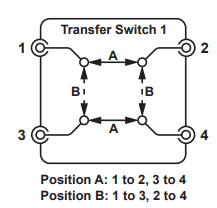
Now, back to our story. We’ve come to the last switch configuration – a matrix. A simple definition could be “any instrument to any test point.” In theory, a properly selected matrix would connect to each instrument in the test system and all of the prescribed test points on your device under test (DUT). It sounds like an ideal piece of your test strategy! But as always, there are parameters to consider. So, let’s examine the different types of matrices.
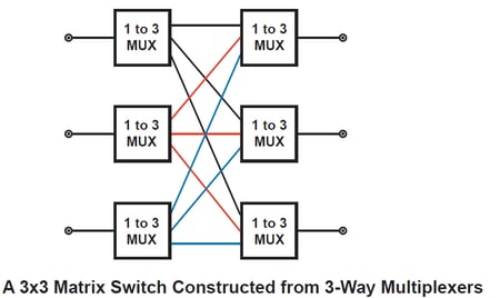
- Basic Matrix –Here is a matrix diagram with six 3 to 1 multiplexers, creating a 3X3 matrix. Note that each channel on the left can connect to any channel on the right. It is important to note that each left channel can connect to just one right channel at a time. This will be important when we look at Cross Point Matrices.
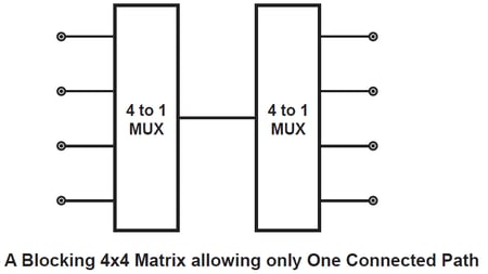
- Blocking Matrix – Some types of matrix switches are configured as blocking switches to reduce complexity. The example below shows a matrix where only one device on the left can be connected to one device on the right at a time. All other inputs and outputs are disabled. Some manufacturers also refer to a blocking matrix as a “sparse” matrix.
- Crosspoint Matrix – Crosspoint switches are arranged in rows and columns– the vertical and horizontal lines are electrical connections– a crosspoint is where the lines cross. A relay is located wherever a crosspoint occurs, allowing the row and column to be connected, hence the name. There is no limit to the number of connections a particular row or column has, but if more than one connection is made simultaneously, the load on the signal source increases.
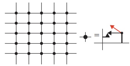
Matrices are also defined by X and Y parameters, with the Y-axis being the horizontal lines and the X-axis being the vertical lines. As you can see here, if I close the crosspoint relay at the top left, the first X-axis connection will be connected to the first Y-axis. With this 5X5 matrix, we can make five separate connections between the instruments and the DUT test points. Of course, it is also possible to make multiple simultaneous connections to either axis. The crosspoint matrix is extremely flexible.
But, the flexibility comes at a cost. The reason is that there are so many relays involved. If I determine I need an 8X64 matrix, the configuration will require 512 relays. A 12X336 will require 4,032 relays! If each relay costs approximately $10, you can envision the expense. But if your test system needs to be highly flexible, addressing multiple types of DUTs, then a crosspoint matrix is your friend.
There are a few caveats to be aware of:
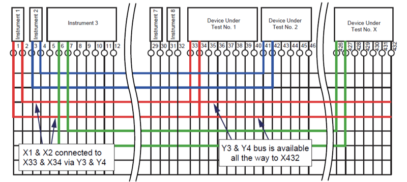
- Analog busses – One option that several manufacturers offer is multiple analog busses. Typically, the Y-axis rows are considered a single analog bus. In this instance, the Y-axis rows connect to all X-axis columns. In some designs, the test engineer can create multiple matrices programmatically by “separating” the matrix into smaller matrices. In this configuration, relays are added in the Y-axis such that multiple Y-axis buses may be connected, each one accessing a section of the matrix’s cross points. The advantage is that the matrix is more flexible in that it can be configured in several different ways as may be needed by the test program for a particular DUT. It may also reduce the number of slots required for a test system by eliminating the need for a second matrix.
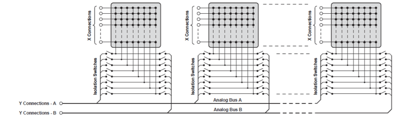
- Stub lengths – One of the downsides of a matrix becomes evident as signal frequencies go higher; Crosspoint matrices always have interconnections across the whole X and Y axes. These can act as unterminated transmission lines or “stubs" at high frequencies.” These can create resonant structures and limit the bandwidth of the switch. The available bandwidth is also dependent on the number of crosspoint switches closed. Several matrix manufacturers use “Isolation Relays” that will disconnect the excess stub length when necessary, thus improving performance. Look for this feature if higher frequencies need to be considered.
- “Stubless” matrices –Stubless Matrices are created from Tree Multiplexers to provide solutions for matrices requiring very high RF or microwave bandwidths. In creating these matrices, they also restrict the connectivity that can be provided. Implementation of Tree Matrixes can be complicated by the problematic routing that they impose on PCB designs because there are large numbers of crossing tracks or by the number of coaxial connections required.
- Two-pole matrices – Two-pole matrices are recommended when a signal needs to be measured with a shielded connection (controlled differential line impedance). For this configuration, DPST relays are used instead of SPST relays. A second example is when you are switching a voltage source and are using remote sense to ensure regulation at the DUT is being sensed—the two-pole arrangement ensures that the sense connection follows the power connection. The other way, and inherently more expensive, to implement a two-pole matrix is to order a matrix with double the number of Y-Axis rows that are needed and program two rows simultaneously.
I think that’s enough for today. Next time, we will discuss several ways to use a matrix and the maintenance questions to ask your vendor of choice.
For more information, check out our SwitchMate ebook and watch the on-demand webinar: Maximizing Reliability in Signal Switching to learn the importance of switching in test systems.
<< View the previous blog post in this series, "Electronic Testing 101: Switch Types and Configurations – Part 2"