It's important to remember that the weakest part of your electronic test system will limit the effectiveness of the test. We’ve talked about the test plan and specifications, relay types, and cables. Now, let’s discuss connectors. The integrity and robustness of the connectors used and the quantity of them in the signal path are crucial. Let’s go a little deeper here.
Connector & Backshell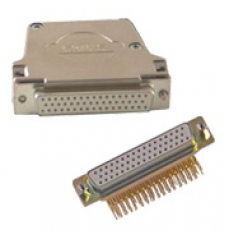 To get from the instrument and/or switching to the unit under test (UUT), there will always be some form of cabling. In the case of the connector to the test system, you will have to use the mating version of the connectors on the front of the modules. After that, the choices are many. For example, will the cables directly connect to the UUT? If so, consider the number of mating cycles the mating connectors are rated at. Many of the lower-cost connectors are only rated for 50 or so mating cycles. In electronic test, it might mean replacing connectors every week! Try to specify connectors with 500 or more mating cycles. Note – connectors in mass Interconnects are rated for thousands of mating cycles. But more on that in a later post.
Wire size and insulation thickness cause physical issues when inserting hundreds of wires into a small connector backshell. Selecting the correct gauge of wire and insulation thickness can go a long way to resolving this and making the finished custom cable assembly more affordable.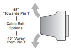
Backshells are available with three different exit options. Consider which direction makes the most sense regarding ease of access and removal and working in tight spaces inside the tester cabinet.
Download or request a hard copy of our FREE SwitchMate eBook for an overview of switching for automated test systems.
Consider the Entire Signal Path 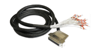 Keep in mind that each connector inserts resistance in the signal path. So, suppose your test system has a bulkhead set of connectors on the cabinet wall. You’ll then have the potential for at least four connectors in the signal path– switching front panel to bulkhead (two connectors here) and bulkhead (again, two connectors) to UUT. All connectors have initial and longer-term resistance specifications. Make sure that you calculate the overall resistance of the signal path. This includes wires and connectors, to see if they will affect the signal integrity. To get the integrity you require, you may have to specify more robust connectors with lower resistance specs.
Watch that Capacitance
A long cable may have a fair amount of capacitance which can damage your switching, PXI instrumentation, or other instrumentation when discharging the energy within the cable. I worked on a defense application where the UUTs were in a chamber, and the cables from the chamber to the tester were 24 feet long! The wiring used polyurethane insulation. Standard Wire and Cable Co shows that this insulation can exhibit up to 6.5 pF per foot. A charge large enough to damage delicate instruments is possible with such long cables. Additional switching had to be added to discharge the cable between tests.
If all of these choices sound complex, they can be. I recommend that you work with a reputable cable manufacturer or become good friends with your component rep who is selling you wire and connectors.
Try our FREE cable design tool to create a custom cable assembly
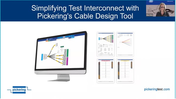
For more information about cables, watch the webinar "Simplifying Test Interconnect with Pickering's Cable Design Tool" and check out our Connectivity webpage.