In our last blog post, "Electronic Testing 101: Switch Types & Configuration – Part 3," I provided details on what a matrix is and several different configurations. Today, I want to provide some guidelines on ways to implement a matrix efficiently.
I trust you remember that a crosspoint matrix is made up of several X and Y tracks with relays at every point where X and Y crosses. The idea is to connect stimulus and measurement instruments to the matrix and all devices under test (DUT). Then the matrix connects the instruments to the DUT test points programmatically. So, what do I need to know before ordering the correct matrix size and wiring it? Well, let me show you!
Things to know before ordering a matrix:
- How many stimulus and measurement instruments will there be?
a. Are any instruments using 4-wire measurements included?
b. Can you use a common instrument ground? Saying “no” here means all matrix connections will be at least 2-wire switching connections.
2. How many DUT test points are there?
3. Will multiple DUTs be tested in parallel? This can increase the number of connections.
4. What is the maximum number of simultaneous measurement connections necessary at any point in the test program?
5. Finally, what are the specs on stimulus and measurement? This includes voltage, current, and frequency.
Once you know the above answers, then you can study relay types.
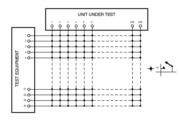 Matrix configuration using the Y-axis for instrumentation
Armed with the above data, let’s configure!
Typically, matrices are available with 4, 8, 16, and in some cases, 32 Y-axis connections. As seen here, many test engineers will consider connecting the instruments to the Y-axis and all of the DUT test points to the X-axis. For a small configuration, this is a logical choice.
Remember in my last post when I mentioned that the cost of a crosspoint matrix is based on the number of relays and that it can be expensive? Let’s assume that this hypothetical test system has 8 stimulus and measurement instruments, of which two instruments are using a 4-wire measurement, and the other 6 are 2-wire, referenced to chassis ground. So, over the course of the test program, we will be switching 14 different instrument connections at any given time.
There are 48 DUT test points per DUT and up to three DUTs in the test fixture. So, that is 144 DUT test points. Typically, that means you will have to order at least 150 X-axis connections.
Now let’s do the math. For 14 Y-axis connections, we need a 150x16 matrix. Multiply the 16 Y-axis connections by 150 X-axis connections times $15 per crosspoint (the cost will vary by relay type), and you have a list price of about $36,000. Have your credit card ready; operators are standing by. 😊
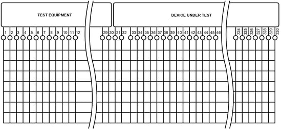
Matrix configuration using the X-axis for instrumentation
But there is one way to lower the cost easily, and this depends on the answer to question #4.
Let’s assume that we will need a maximum of eight simultaneous instrument connections at any one time, and it doesn’t matter if the program uses the 2-wire or 4-wire instruments. And if we connect all of the instruments and the DUT test points to the X-axis, as seen here, we only need a 160x8 matrix– the closest configuration is a 192x8 matrix. Applying the same math as we used in the last paragraph, we are closer to $23,000– a savings of about $13,000! So, in many applications, connecting everything to the X-axis saves money. Just keep in mind question #4.
Next time, let’s look at programming issues and the dangers therein.
For more information, check out our SwitchMate ebook and watch the on-demand webinar: Crosspoint Matrix Switching for Functional Test
<< View the previous blog post in this series, "Electronic Testing 101: Switch Types and Configurations – Part 3"