As discussed in my last post, Electronic Testing 101: Questions to ask when Reviewing Test Specs or Outlining Reqs, no one relay will operate from say millivolts to 1,000 volts at a frequency range to DC to 18 GHz. As more and more devices combine digital, analog, and RF/Microwave, you as a test engineer will likely be required to select many different relay choices for your test system. So, let's look at the various relay types in the market, where they excel and where they should not be used.
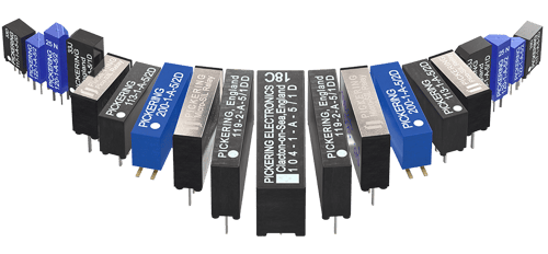
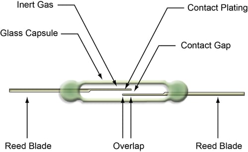
- Reed Relays –These are deceptively simple devices in principle. The reed switch has two shaped metal blades made of a ferromagnetic material (roughly 50:50 nickel/iron) and a glass envelope that holds the metal blades in place and provides a hermetic seal that prevents contaminants from entering the critical contact areas inside the glass envelope. The hermetic seal makes reed relays a good choice in hazardous environments since sparking does not create a safety problem. The mechanical life of a reed relay is very long, typically more than 10 to the ninth operations for reed relays manufactured by Pickering Interfaces that are designed for use in low current and medium current applications. Reed Relays can be selected for applications with high voltage of up to 12.5 kilovolts and current under 1 Amp or 1 to 3 Amps at a much lower voltage.
If you need help finding the correct reed relay for your test system, try our relay division's Reed Relay Selector tool.
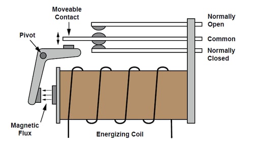
- Electro-Mechanical Relays (EMRs)– EMRs are widely used in the industry for switching functions and can often be the lowest cost relay solution available to users. These are the most common form of relays available and can be used for many functions, including high power applications of up to 20 Amps. Most relays of this type are not hermetically sealed, making them unsuitable for applications where they are required to switch low-level signals over long periods or in environments where flammable gases may be present. Some EMRs may include a specification for low-level contact switching contact resistance that is worse than when switching high-level signals. So, keep this spec in mind if there is a broad range of voltages being switched by EMRs. EMRs can have much higher ratings and a lower contact resistance than reed relays because they use larger contacts; reed relays are usually limited to carry currents of up to 2 or 3 Amps. Because of their larger contacts, EMRs can also often better sustain current surges. The number of operations is less than reed relays, often only 10 to the fifth operations. For most general-purpose applications, EMRs are ideal.
- Solid-State Relays – Solid-state relay refers to a class of switches based on semiconductor devices. There is a large variety of these switches available. Some, such as PIN diodes, are designed for RF applications, but the most commonly found solid-state devices that compete with reed relays are based on FET switches. A solid-state FET switch uses two MOSFET in series and an isolated gate driver to turn the relay on or off. All solid-state relays have a leakage current specification. Consequently, they do not have as high an insulation resistance as EMRs and reed relays. The leakage current is also non-linear but predictable. The on resistance can also be non-linear, varying with load current. There is a compromise between capacitance and path resistance. Relays with low path resistance have a large capacitive load (sometimes measured in nF for high-capacity switches) which restricts bandwidth and introduces capacitive loading. In my opinion, the virtually infinite life of Solid-State switching is suitable for applications like Highly Accelerated Life Screening (HALT) and Highly Accelerated Stress Screening (HASS) as tests can go on for weeks and even months.
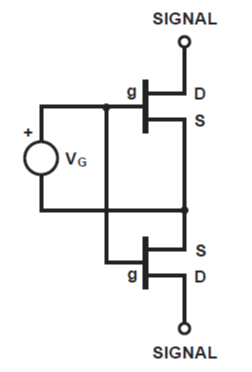
Solid state relay using Two N Channel MOSFETs with an Isolated Gate Drive
In my last post (Testing 101: Questions to ask when reviewing test specs or outlining requirements), I talked about understanding what the test specifications are. Now that we are talking about relay types, the key specs to focus on are:
- Voltage
- Current
- Bandwidth
- Power
- Switching life
Voltage, current, and bandwidth are probably the most obvious. Where you can get in trouble is the last two. Ohm’s Law tells me that if I select a relay rated at 150 Volts at 1 Amp, I expect to switch up to 150 watts, right? That could be wrong. If the relay is rated at 150 Volts at 1 Amp AND 60 watts of power, that means that you can switch 150 volts OR 1 Amp. Any spec in between is derated. Finally, relays like reeds and EMRs are rated for the number of cycles at a given load. So, a reed relay rated for 10 to the ninth cycles at a low power application (100ma or less) might be rated at 10 to the sixth cycles at full power rating– several orders of magnitude less— this needs to be factored into your maintenance schedule.
As always, comments and/or questions are welcome. If this blog series is valuable to you, be sure to share the link with your colleagues.
For more information about relays, check out our other resources such as the "What is a Reed Relay?" video and our Switchmate eBook. Watch the on-demand webinar: Maximizing Reliability in Signal Switching to learn the importance of switching in test systems.
<< View the previous blog post in this series, "Electronic Testing 101: What to Ask when Reviewing Test Specs or Reqs"