When ICs replaced vacuum tubes and CRTs were replaced with flat LCD screens, test engineers probably thought that working with high voltage was a thing of the past. Well, guess what? It’s back!
Designers in fields as diverse as semiconductor manufacturing, gas analysis for mining applications, defibrillators, solar energy, and EVs are all looking for switching modules with higher stand-off and switching voltage characteristics. As always, one size rarely fits all, and there are some essential considerations that users should be aware of when specifying a switching module for high voltage tests. So, let’s look at some areas of concern.
The configurations of switching modules are much the same as switching for lower voltage applications- uncommitted switches, fault insertion, multiplexers, and matrices. There are also reed relay and EMR (electromechanical relay) solutions. The most apparent difference is switching density. Because of voltage standoff issues, relays are spaced much farther apart. For example, a single-slot PXI module switching up to 9 kV may have a maximum of 14 relays fitted.
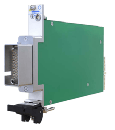
Fig.1 - High voltage PXI module
Expanding a switch design to use multiple slots can, of course, expand the configurations. But when you consider that a single-slot PXI module can hold up to 528 low voltage relays, the limitation becomes very clear. Other modular formats such as LXI can give your test system more real estate to work with, but the density will still be less when compared to low voltage applications.
Relay Types
- Reed relays
Reed relays tend to be a good fit for high voltage applications. Reed relays feature a hermetically sealed switch, and the contacts operate in a vacuum or an inert gas. Therefore, the tracking distance can be much less than for devices like EMR relays that operate in free air. Leakage currents are low for reed relays, with isolation resistance of up to 1015Ω.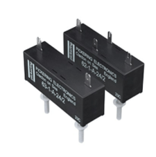
- Electromechanical Relays (EMRs)
With EMRs, the contacts are open to the environment. This can be an issue with contact contamination and operating EMRs in a hazardous situation, such as testing on a flight line when jet fuel fumes are likely present. - Solid-state Relays (SSR)
SSRs suffer from high leakage currents and susceptibility to high voltage spikes, which become more problematic at higher voltages.
Hot or Cold Switching
Reed relays generally have a higher carry current (cold switching) rating than their ‘hot’ switching current rating. Looking at figure 3, 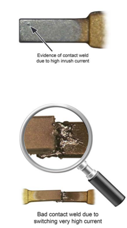 contact damage occurs during hot switching, caused by the resulting arc across the contacts as they open or close. A severe current overload will quickly melt the contact area causing the two surfaces to fuse, creating a hard weld as soon as the contact closes.
Specifications
Like the selection of any other switching system, your engineering test specification will dictate the switching system. Careful analysis of the datasheets of your switching system of choice is essential to study before making a purchase.
Specifications to pay close attention to include:
- Voltage – Usually, a reed relay will be rated at DC voltage. If a device is rated at 3000 V for DC peak voltage, the RMS value will be 3000 / √2.
- Peak Voltage – This is usually the same number as the DC operating specification. However, compared to the maximum DC voltage specification, the AC source is generally recommended to be fully isolated from the mains AC supply.
Fig.3 - Damaged relay contacts due to excessive
hot switching or exceeding relay specifications
- Hot Switching Limits– When hot switching, it is vital to ensure that the product of the voltage and current to be switched does not exceed the overall switching power rating of the relay. For example, consider a relay with a maximum switching power rating of 50 W and 0.25 A. If the application requires the relay to switch at 5000 V, the maximum current will be limited to 10 mA and not 0.25 A, as that would necessitate a power rating of 1,250 W.
Download or request a hard copy of our FREE SwitchMate eBook for an overview of switching for automated test systems.
Now you are armed with enough knowledge to select your switching system. In my next post, we will talk about fixturing and cabling and the pitfalls that lay ahead. And remember... Don't touch that bare wire!
<< View the previous blog post in this series, "Electronic Testing 101: The Hard Part of Software in Complex Switching Systems."
View the next blog post in this series, "Electronic Testing 101: The High Points of High Voltage Testing - Part 2">>