In our last post about high voltage testing, we talked about relay types, density, and specifications. Now let's look at the possible test system "frying" issues that your fixtures and cables can cause if you are not careful. Here are some things to watch out for:
Capacitive Inrush Currents
High voltage relays fail because the circuit's reactance (capacitance or inductance) has not been adequately considered. See Figure 1.
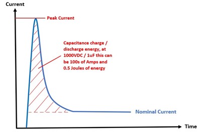
Fig. 1
Any capacitance in a high voltage circuit can be charged or discharged by the closing switch - if there is no load to limit the inrush, the current can be 100s of amps. This energy can cause significant damage to the relay contacts. Therefore, either the nature of the capacitance in the circuit needs to be considered, or protection must be included.
Allow A Safety Margin
Manufacturers rate devices at a voltage level. For levels significantly above 10 kVDC for switching or 15 kVDC for isolation, it is inadvisable to push any switch module to the specified maximum limit. When the part is new, it should perform according to the datasheet, but throughout its life, arcing will occur, primarily when hot switching is employed. Metal transference will take place between the contacts. This can cause a build-up on one contact, reducing the contact gap and hence the voltage stand-off. By allowing a margin of at least 10%, the relay can be expected to perform reliably throughout its life.
Read our previous blog post, "Electronic Testing 101: The Different Types of Relays and their Specs" for an overview of relays.
As there can be potentially dangerous voltages present on switch connectors, whether the test system is actively running a test program or even at the end of a test program because of residual capacitance, a safety interlock is implemented on many manufacturers’ switching systems, which will open all relays should an event selected by the test engineer occur (example, activating the mass interconnect interlock when the test fixture is released) to protect the operator. The signal can also be used to disable the high voltage source.
RFI Suppression
In some cases, effective RFI suppression integrated into the switch module or as part of the test system can extend relay contact life in hot switching applications and control surges caused by high voltage transients in cold switching applications. RFI suppression also ensures a module’s safe operation when connected to a high voltage source via cable assemblies that might otherwise generate additional transients or RFI problems. However, suppression components can result in reduced bandwidth and a slightly higher path resistance than standard designs.
Corona Discharge
Wikipedia states that a corona discharge is “an electrical discharge caused by the ionization of a fluid such as air surrounding a conductor carrying a high voltage.” In some situations, this discharge can be visual (seen as a bluish glow) and aural. The discharge can create corrosive gasses that can damage connections and be hazardous to the test system operator. Corona discharge can occur in voltage ranges from as little as 2 kV to 6 kV, depending on the application. While this is primarily prevalent in high voltage transmission lines, small corona discharges during test are possible. The possibility of corona discharge can be minimized by using the correct insulation.
Cables and Connectors
Selecting the correct wire insulation is essential for high voltage applications. For example, standard PVC (polyvinyl chloride), a common insulation, is only rated to 1,000 volts. IEWC Global solutions (iewc.com) recommends Polyethylene for cables up to 9 kV. Polyethylene is very good insulation as it offers a low and stable dielectric constant over all frequencies and a very high insulation resistance.
Connector types are equally important. The fundamental limitations are pin spacing in the connector and the dielectric used to hold the pins. Connector specifications to consider are the rated voltage and current, the withstand voltage (similar to the cold switch rating of Pickering’s switch modules), breakdown voltage, and the insulation resistance.
As the dielectric is one of the key contributors to insulation, if you have very few high voltage signals to connect, you may want to “Checkerboard” your pin connections. In this example of a 24-pin high voltage connector (Figure 2), you can see that no signal is directly adjacent to another. As the space between signals is doubled, the isolation spec of the connector is significantly increased. As only 25% of the pins are used, it is a limitation in some applications.
.png?width=213&name=fig%205%20HV%20(2).png)
Fig. 2
Mass Interconnect systems from companies like MacPanel and Virginia Panel have connectors rated for an operating voltage of up to 1.5 kV DC (1.25 kV AC) and a withstand voltage of up to 4.5 kV DC (3.75 kV AC); consult your mass Interconnect vendor of choice before making a selection. So, a separate connector for the HV connections is necessary for applications above these voltages. This brings up a point – if you use a mass interconnect in your test system and need to use a separate connector for your HV connections, pay close attention to the number of mating cycles the connectors are rated to. Many high voltage connectors are rated to just over 100 mating cycles, unlike mass interconnects, which are rated for thousands of mating cycles. A connector like this will necessitate added maintenance as frequent replacement may be necessary.
Important Specifications
High voltage connectors cite two specifications: Typical Breakdown Voltage and Dielectric Withstanding Voltage (DWV). Breakdown voltage is relatively straightforward: applying this voltage will cause catastrophic failure in your connector, cabling… and possibly instruments and DUTs.
DWV is probably the most important specification you will want to know. A spokesperson for Virginia Panel states, “The DWV test consists of applying a voltage higher than rated voltage for a specific time between mutually insulated portions of a connector or between insulated portions and ground. For standardization purposes, the withstanding voltage is established as 75% of the minimum breakdown voltage of the connector. It is suggested that the operating rated voltage of the connector be established as 1/3 of the withstanding voltage.”
A spokesperson from MAC Panel also added that “the environment must always be included in High Voltage connector system design as the relative humidity, temperature, and composition of the gases around the contacts will affect the positive outcome of the test. All the figures we publish are assumed to be 50% humidity and air.”
In summary, an excellent high voltage test system design combines the application’s specifications, wire type, insulation, discharge and RFI suppression, environment, and connector types.
For more information, check out our FREE SwitchMate ebook
View the previous blog post in this series, "Electronic Testing 101: The High Points of High Voltage Testing - Part 1">>