The automotive industry has aimed for active vehicle safety for over 40 years. Features like ABS (Anti-lock Brake System), adaptive cruise control, and BLIS (Blind Spot Information System) have significantly enhanced vehicle safety, allowing the driver to focus on other aspects of the driving experience. In recent years, R&D has focused on taking complete control of the vehicle, making the former driver merely a passenger.
This program is called ADAS (Advanced Driver Assistance Systems). Still under development, ADAS utilizes a range of integrated systems to determine the vehicle's direction and environment, as well as to manage traffic, weather, and other adverse conditions. ADAS requires many electronic subsystems to make these decisions. Advanced testing strategies are also being developed to ensure that the vehicle works correctly in the real world. This article focuses on fault testing the Ethernet channels of an ADAS control module, rather than the actual ADAS control module itself.
ADAS Overview
ADAS is being rolled out in stages as systems become operational. The SAE (Society of Automotive Engineers) is a standards body that defines specifications and rules for most systems in the transportation industry. The SAE J3016 specification defines six classes of automated driving capability, ranging from no automation to complete vehicle control. While all the systems necessary are defined, cars have only reached SAE 2+ and SAE 3 in 2024, and there is still a long development cycle to reach SAE 4 & 5.
ADAS requires the use of video and infrared cameras, ultrasonic sensors, and enhanced sensing systems such as Li DAR and RADAR to understand the environment around the vehicle (Fig. 1). As GPS is not accurate enough for automated driving (GPS is accurate to 4.9 meters or 16 feet), high-density digital maps with 10 cm accuracy use a rough approximation of the vehicle’s location from GPS, and the HD maps take over [Note: ADAS uses the GPS PPS (Pulse Per Second) signal to synchronize all systems.]
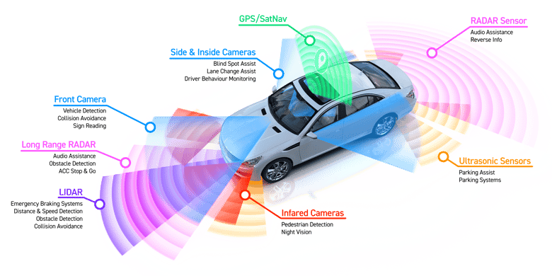
Figure 1 – Typical ADAS Sensor systems
The important takeaway from this graphic is that all the sensors generate a lot of data. Add to that the data from the HD map, and you are dealing with multi-gigabytes of data per second. So, a high-speed, synchronous, highly secure, and reliable network configuration is required.
To meet these requirements, a new standard known as 10GBASE-T1 for Automotive Ethernet (IEEE Specification 802.3ch) has emerged. In future developments, it is anticipated that speeds up to 40GBASE-T1 will be specified for high-performance vehicles. Vehicle networks usually consist of multiple 10GBASE-T1 channels arranged in a star configuration. Depending on the manufacturer, one Ethernet channel may be allocated to each sensor array. Multiple sensor arrays may be assigned to one Ethernet channel for lower-speed sensors like ultrasonic and infrared cameras.
Creating separate Ethernet channels is part of the redundancy and recovery strategies for the ADAS subsystems. For example, if a network channel fails, some assistance systems—like LiDAR, park sensors, and cameras—can fail and get deactivated. Others, like RADAR and short-range cameras, will shut down the entire system. So, keeping these sensor systems separate simplifies some decision-making.
From a network testing standpoint, the design verification and production tests must verify that any fault on one or more Ethernet channels causes a system error or shutdown. Each 10GBASE-T1 channel operates over a single shielded twisted-pair cable in full-duplex mode, transmitting and receiving on the same pair. So, each pair and—depending on your test strategy—each wire of each pair may be tested separately. At present, there are few commercial options for verifying potential Ethernet channel faults at these data rates. However, international safety agencies like SGS developed SOTIF (Safety of the Intended Functionality), a series of ISO 21448 related services. This is a new safety standard that relates to automated systems and autonomous cars, and will require proof of design verification. So, solutions that are repeatable, accurate and commercially available are needed.
Our latest Multi-Gig Fault Insertion Switch Family (models 40/42-205), available in both PXI and PXIe formats, is the first in the industry to feature 4 or 8 impedance controlled 2-wire channels, capable of addressing up to 10GBASE-T1 Ethernet requirements. In the default position, the channels directly pass through the module without significant signal loss. The in-line switches are based on the latest micro-electromechanical system (MEMS) switching technology with a high bandwidth of 6 GHz, typically, but capable of 25 or 40 Gbit Ethernet in future releases, low insertion loss and VSWR, in addition to a long operational life of >3 billion operations and very fast operation. Relay cycle counting is included to alert test engineers when the modules are nearing end-of-life.
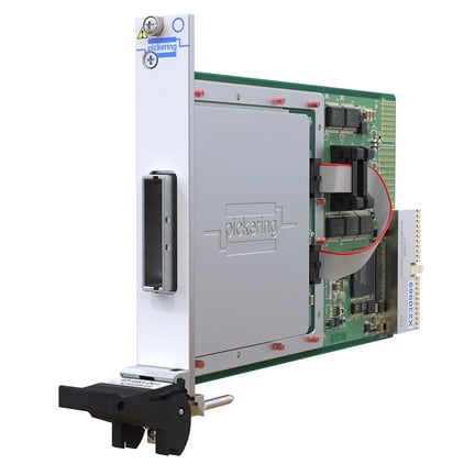
Figure 2 - Pickering Interfaces 40/42-205 Multi-Gig1 MEMS Fault Insertion Switch (PXI Version Shown)
In the fault insertion mode, the module can simulate the following fault conditions:
- Open channel or individual wire
- Channel or individual wire tied to GND
- Channel or individual wire tied to VCC
- Channel or individual wires shorted together
- Partial short to GND, VCC, or other channel(s)
Let’s examine how each fault is created.

Figure 3 shows a schematic diagram of the 40/42-205-004 four-channel fault insertion switch unit (FIU) with four 2-wire I/O channels.
Fault Insertion - The principle is simple: switching modules sit between the simulator (test system) and the DUT (Device Under Test) (e.g., ECU/ADAS controller) and either pass the signals through unchanged or add a range of fault conditions.
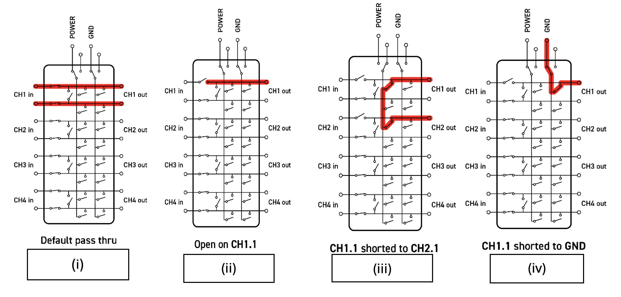
Figure 4 shows an FIU Channel with two single wires and two fault buses.
In Fig. 4(i), the FIU is in the default mode of operation, where all signals are passed through. In Fig. 4(ii), an open circuit is being simulated on channel 1; in Fig. 4(iii), there is a pin-to-pin short between channels 1 and 2; and in Fig. 4 (iv), a short-to-ground fault simulation is produced on channel 1.
Resistive faults can also be simulated by inserting an external resistance via the fault buses (Fig. 5). It is important to note that, unlike the in-line channels of the module, which are 100 Ω impedance matched, the fault buses are only suitable for resistive faults or shorts to VCC and/or GND. You cannot, for example, connect an alternative Ethernet channel to the DUT via the fault bus, as the bus connections are not impedance controlled.
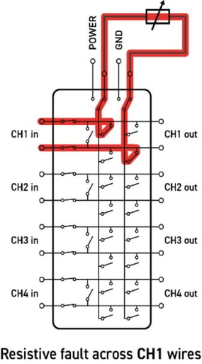
Figure 5 shows a resistive fault across CH1 wires.
Mating Connectors, Cabling and 40-205-900/901-800 Interface Board
The front panel of the 40/42-205 features a SAMTEC Eye Speed® connector, as seen in Figure 6. This is a mass-terminated cable, so separating Ethernet pairs requires a breakout assembly. We provide the cable from the module to the breakout in either 0.25 m (P/N A062YMR-062YMR-0A025) or 0.5m lengths (A062YMR-062YMR-0A050).
Due to the mass-terminated nature of the Eye Speed connector, a Pickering-designed interface board is recommended for user connections to the 40/42-205 fault insertion module. Using four Rosenberger E6S20D-40MT5-Z connectors (Figure 7) and a 9-pin male D-type for inserting fault signals, the bench-top 40-205-900-800 breakout assembly (Figure 8) distributes the signals from the module’s Eye Speed connector. Optionally, you can order the breakout assembly in a 19” rack mount chassis.
The overall insertion loss of the Eye Speed cables and the interface board depends on the configuration and cable length used. We can define the loss as “7dB (typical)” at 4 GHz. Your system integrator is responsible for acquiring the cabling for the Rosenberger connectors to the DUT. They are available in different lengths from many distributors.
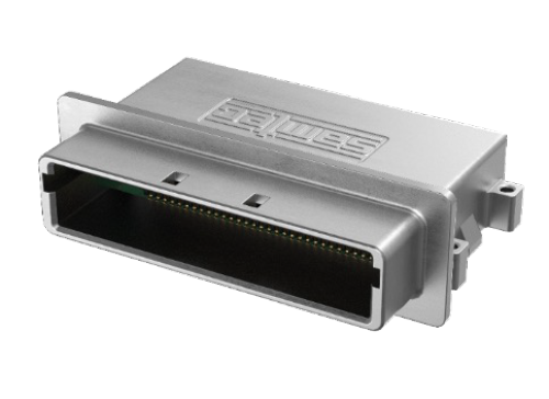
Figure 6 – SAMTEC Eye Speed®
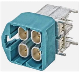
Figure 7 - Rosenberger E6S20D-40MT5-Z connector
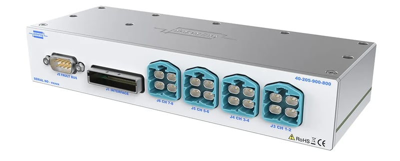
Figure 8 – 40-205-900-800 bench-top breakout assembly.
Interfacing the 10GBASE-T1 Fault Insertion Switch to the DUT
Given the data rates of 10GBASE-T1 Ethernet channels, cable lengths, and the proximity of the FIU switching, need to be as short as possible. It is recommended that the 40-205-900/901-800 interface board be mounted within one-half meter or less from the 40/42-205 modules and as close to the DUT as possible. Cables from the Rosenberger connectors should also be as short as possible. Note that if a mass interconnect is used, measure the overall loss per channel of the entire circuit (40/42-205 FIU, Eye Speed cable, interface board, mass interconnect and Rosenberger cables) to ensure adequate signal strength is present at the input of the test system’s Ethernet analyzer instrumentation.
Conclusion
In ADAS vehicles, a massive volume of data is generated and routed to the ADAS controller. The management of this data is critical to vehicle and passenger safety. So, testing network integrity and its response to failures caused by interconnection faults is equally vital. Fault insertion is a valuable tool that test engineers should consider when testing the robustness of the Ethernet design and the production quality of the DUTs being tested. This tactic should be considered for NPI testing, as well as a subset of production test. Our 40/42-205 fault insertion modules and 40-205-900/901-800 breakout assemblies offer effective modular solutions for your test strategy.