Switching Modules are at the heart of the modern ATS, providing many benefits to production teams. These include fast test times, accurate and repeatable test results, and minimizing potential operator error. However, switching modules that use mechanical relays have a finite life and may fail due to accidental damage or wear and tear. These failures can occur at inopportune times in a production cycle. It can be challenging to isolate the root cause of the failure using in-house developed tests, resulting in a lengthy mean-time-to-repair (MTTR).
In this blog post, we will examine a typical switching subsystem lifecycle. Our goal is to show you:
1. Why switching systems fail
2. And examine the ways to minimize downtime
We'll look at tools that speed up the MTTR and discuss ways to make sure your diagnostic information is accurate. Then, we'll discuss techniques for maintaining switching systems, including diagnostic techniques, and preventative and predictive analysis.
Let's get started.
Switching
When a relay is either opened or closed while carrying a signal, we say that the relay is “hot switching.” Hot switching is often necessary for a test application, but it also results in the most wear and tear on the relay. Relays that hot switch signals are subject to voltage spikes and generally run hotter. These conditions will lead to early-life failures. Hot switching at 50% maximum load capacity can reduce relay life by up to three orders of magnitude. For reed relays, typical operating life under light load can be up to 5 billion operations but only 5 million operations at a heavy load.
It is not always obvious how much voltage or current a relay is hot switching; for example, if a relay connects a low-impedance source to a high-impedance load, you would expect the switched current to be relatively low. However, if the cabling or load has significant parasitic capacitance, there may be a high-surge current through the relay when it closes as the source charges the capacitor.
A relay may also experience a high surge current when it connects a source to a capacitive load carrying a charge from a previous state. This might occur, for example, when a switching system reverses the polarity on a Unit Under Test (UUT) or if a previous operation has left a charge on a high impedance load. For this reason, some cable test systems provide a way to discharge any residual charge on the cable assemblies before actuating the relays. However, as mentioned earlier, the specifications for switching modules typically only define a maximum hot switch voltage/current/power when the module is connected to a resistive load. So it should be noted that if long cables or other capacitive loads are attached, the rating may be affected.
In short, having a solid understanding of the use case is necessary when trying to predict the life expectancy of your automated switching system that extends beyond the manufacturer’s specifications.
Common Failure Symptoms
The most common failure symptoms that relays and switching systems will exhibit are:
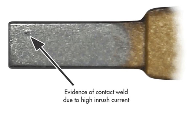
- Welded Contacts
Welded contacts are usually caused when hot switching generates high inrush currents that exceed the manufacturer’s specs. The resultant heat will create molten or soft metal in the contact area. This causes the welding to occur. In these instances, the current-carrying track on the relay circuit board may also be damaged as it has a finite amount of current that it can pass.
- Contacts Having Variable or Intermittent Contact Resistance
This occurs particularly at no-load or low current levels because of contamination build-up and erosion of the contact materials. This can also occur when the contacts are pitted as a result of hot switching. - Failure to Close
This type of failure is caused by severe erosion of the contacts and debris build-up on the contacts. Having debris on the contacts is more of an issue with electro-mechanical relays as their contacts are exposed to air, whereas reed relays have hermetically sealed contacts. In less common cases, the IC driving the relay control lines may no longer be functional, preventing the relay from operating correctly.
Hot switching problems frequently occur during the test system program debugging phase. Programming or construction errors outside of the switch system can result in accidental hot switching events which overload or damage the relays during the commissioning of the system. The worst scenario is where the contacts are damaged but still function, as the test engineer will not be aware that the working life of the switch module has been impacted.
Diagnosing a Switch Failure
The most common method to diagnose a switch failure is the self-test method mentioned above system. This is typically achieved by wrapping system source/measure equipment through system switches to identify the failed module. Once it is believed that a faulty module has been identified, it is usually swapped with a spare known good unit. The process to generate a PO is started so that the faulty unit can be sent back to the manufacturer for repair. The manufacturer will usually use the end-user self-test report to help identify the root cause of the failure for a quick repair.
While the test system may be operational and production is up and running again with the known good board, the upstream diagnosis could have created a ripple effect of frustration for others in the organization. For example, the process of swapping modules may have masked the root cause of the failure — possibly a loose cable connection or contact. In this case, a sound module is returned for repair, and the dreaded ‘no-fault found’ cycle will have kicked off. The self-test report may only identify the module as failed with no description of test conditions, which could lead down the no-fault-found path once again. In either case, this is a time-consuming, frustrating, costly, and overall inefficient exercise for the production team and the switch module manufacturer.
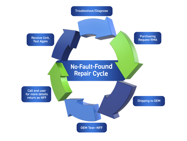
'No-Fault Found' Cycle
Diagnostics Test Tools, BIRST and eBirst
Many switch system manufacturers now incorporate self-test utilities into their products to improve fault diagnosis efficiency; however, if your vendor does not provide this capability, you’ll need to budget time and money to build your own. Pickering incorporates Bulit-in Relay Self-Test (BIRST™) capability into many of our high-density matrix products. BIRST is a combination of internal source/measure circuity and a standalone software application. It provides a quick and easy way of identifying relay failures. The user disconnects the switch module from the DUT and test instrumentation, and runs a supplied application program. Then, the BIRST software utility calculates path resistance and compares against expected limits to identify any defective or suspect relay measurement paths within the module. The BIRST test is a rapid way of identifying whether or not a switch matrix is fully functional or not.
Click here to learn more about our diagnostic test tools
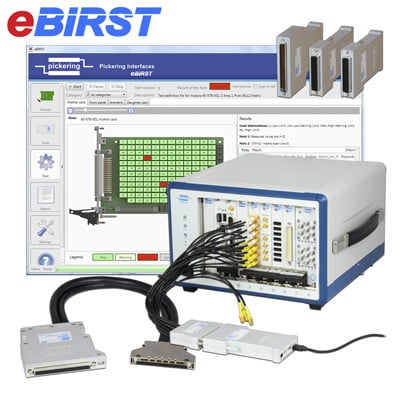
On configurations other than matrices — take a switch module with 50 independent relays — there is no easy way to establish a through path between the BIRST source and measure circuitry without adding additional relays to the system. To address these shortcomings, Pickering’s eBIRST Switching System Test Tools provide a much higher diagnostic accuracy and switch module coverage.
-
Similar to BIRST, eBIRST is a combination of source/measure circuitry with a standalone software application. The significant difference is that the source and measure circuitry is provided on an external adapter that is powered through a USB port on the test system controller PC. In addition, each switch module has a test definition file that identifies the switch architecture and test sequence.
- The eBIRST tools can test any Pickering switching system that uses mechanical relays with precious metal contacts (typically contacts with a rating of 2A or less) or solid-state relays. eBIRST is especially suited to modular switching systems such as PXI as a faulty module can then be easily swapped or quickly repaired.
- The BIRST/eBIRST diagnostic test tool is not intended to displace user-developed self-test applications entirely. The system-level tools that typically use an external DMM and loopback mechanisms help identify a potentially faulty switch module and identify cable harness faults. Pickering’s test tools conduct their tests when the UUT and instrumentation are disconnected from the switching system. If they find no faults and a system-level tool does find faults, the problem is likely to be with the interconnection system. The user does not have to create software to diagnose switching faults — only interconnection faults — considerably simplifying the design task for system self-test.
Path Resistance
It is obvious when a relay reaches a point where a contact has welded or fails to close because of a contact failure. What is much less clear is when a relay is still functioning but whose performance is degrading, and different users may have different perceptions. In general, for most switching systems, the switch assembly has two principal sources of path resistance: relay contact resistance and connection to the relay from the user connector (often a PCB track; sometimes mainly a wire). The distribution of this resistance is variable from module to module, and the total figure is detailed in the switch module specifications as the Initial Path Resistance. The maximum allowed resistance of a closed path is usually stated at maximum operating temperature (it generally increases by 0.4% per °C) when the switching system is manufactured. We measure every path covered in the datasheet in a cold switch test at an appropriate current for the relay.
Once in use, the path resistance is stable with time, and it may even drop as the contacts "bed-in" to each other with use. Eventually, the resistance begins to be less stable and generally starts to increase. The problem then is what is the EOL point? As a rough guide, we will typically start to ask questions about a relay if the resistance of its path has increased to twice the initial path resistance. Taking a typical design where 30% of the path is relay resistance, then given the PCB tracks or wires are unlikely to have changed, the relay contact resistance will have increased by almost a factor of six.
Pickering’s guidance remains that relays in paths that have doubled the initial path resistance specification on the datasheet should be considered to be nearing the EOL. Still, in reality, they may have considerable life left. The only absolute end of life is a failure to open or a failure to close. Anything else may be application-dependent.
Conclusion
Design of an ATS requires careful planning and must include a system test and sustainment strategy. To ensure that an ATS is fast, accurate, and reliable, the switching portion requires careful selection, as the wrong relay types can fail prematurely or provide inaccurate measurements. A modular architecture provides for quick ATS repair and puts the system back online faster. When possible, maintain a spares inventory of critical switching modules. Finally, a diagnostic plan to verify switching system operation and find defective relays quickly helps ensure a long lifecycle for your ATS and assure maximum uptime and short MTTR.
For more information about switching, check out our Switchmate eBook and watch the on-demand webinar: Maximizing Reliability in Signal Switching.