Several substantial changes in electronic technology over the last twenty years or so have brought about new strategies for automated test. First is the increasing use of electronics to provide active safety in transportation vehicles. Another, that is more pervasive, is the increased amount of software being embedded in individual ECUs (Electronic Control Units). In the case of active safety, there is a wide range of standard features and options that make your car or truck safer to drive. ABS (Antilock Braking System) and Air Bags initially come to mind. But there are so many other options today. For example, there is BLIS® (BLindspot Information System) which warns the driver when accidentally pulling into a lane where a vehicle is already in your planned Path, Adaptive Cruise Control, and so on.
Now let’s talk embedded software. To make ECUs smarter, smaller, and more autonomous, Microprocessors and FPGAs (Field Programmable Gate Arrays) are implemented. These devices have an extensive amount of computer code that is designed to make the ECU more intelligent and autonomous.
Due to all of the features and options available in vehicles, during the ECU's development, the ECU is typically exercised by a test system that simulates the real-world environment in which the ECU will operate– this is known as Hardware-in-the-Loop simulation (HILS). Stimulus instrumentation simulates the ECU’s sensor inputs and measurement instrumentation is used to capture and verify the ECU control outputs. Safety-critical controllers will usually go through a certification process where a series of faults are introduced and the ECU response is checked to see that it operates in a safe and predictable manner.
To learn which environmental situations can be simulated, check out our other blog post, "What is a Programmable Resistor?"
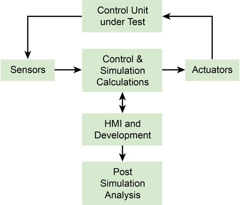
Hardware in the Loop Simulation
To inject the faults, a manual patch panel is often employed. Cables are used to connect the ECU’s I/O lines to stimulus and measurement instrumentation. The I/O lines may be disconnected to simulate open-circuits or tied together to simulate short-circuits to ground, voltage sources or other I/O lines. An engineer moves the patch cables to simulate a desired fault and then measures the results. However, this arrangement has many inherent disadvantages.
One obvious issue is size, as patch panels tend to be large. The operation is also slow and prone to error, leading to a lack of repeatability. Being able to quickly and precisely reproduce a failed test condition is a major advantage and automating this type of test secures the best way of producing a traceable report, free from human error.
The ability to gain software control of both instrument routing and the insertion of real-time electrical faults greatly enhances the testing process. The principle of fault insertion is simple– the switch modules intercept wires between the test system and the ECU and either pass the signals through unchanged or add a range of fault conditions.
For example, take a simple fault insertion switch with six I/O channels. Under normal operation, the thru switches between the test system and the ECU under test are all closed.
- I/O connection disconnected
- I/O connected to one of two fault signals, usually GND and VCC.
- I/O connections shorted together via the fault bus
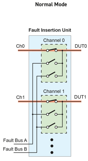
In Normal Mode, no faults are inserted. As seen here, the instrumentation is directly connected to the DUT. A normal Go/No-Go test is run in this mode.
Consider selecting a vendor, such as Pickering, that has a wide range of specifications to suit specific ECU I/O characteristics, including high channel counts, multiple fault buses and signal connections, current handling up to 40A and bandwidths to support high-speed differential signals such as CAN & Ethernet. The modules should be compatible with real-time system software such as National Instruments LABView RT & Veristand or MATLAB’s SimuLink.
To add flexibility to HILS Fault Insertion applications, we supply a modular break-out system which combines small patch panels with our PXI fault insertion modules. A user can experiment by manually injecting faults into the system using the patch panel terminals, and once they are happy with the results, the test connections can then be automated via the associated switch modules.
In conclusion, Fault Insertion switching is an important feature of an ECU test and verification strategy, especially in safety-critical applications.
Want to learn more about automating fault insertion tests, and Hardware-in-the-Loop simulation? Check out our FREE Switchmate ebook