Simplifying Test Interconnect with Pickering’s Cable Design Tool
Once instruments and switching products have been chosen for a test set-up, the interconnect cabling needs to be selected and/or designed. This can be a complex process resulting in a significant investment in time and money, and in some cases, even exceeding the initial purchase cost of the switching modules.
In some cases, you may be able to purchase off-the-shelf cables quickly. But in a complex test system, cable design is probably the last task when developing a test. And because proper cabling is critical, this design needs care and expertise. Depending on the application, the test engineer must consider test specifications, such as voltage, current, temperature, insertion losses, and more. From there, the engineer needs to determine the connections between the instrument and the Device Under Test (DUT) and select connector types, backshells, wire length, and wire types. Unless the test engineer is a cabling expert, researching wires and connectors can be daunting.
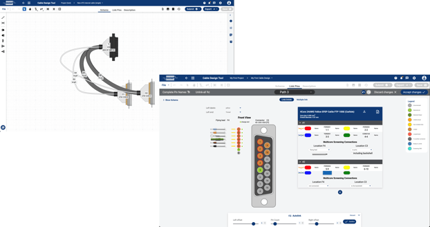
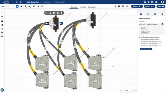
Since we launched our online Cable Design Tool in 2016, it has become a valuable utility to shorten development for test engineers designing custom cables for electronic test systems. Our extensive library of wire, cable, connectors and backshells, coupled with an intuitive user interface, has made configuring custom cable design much more straightforward than other software applications or manually creating them.
The latest version of the Cable Design Tool features a similar look and feel to the original but has many new features based on our users’ feedback. As a leader in test and measurement switching and simulation since 1988, we fully understand the importance of high-performance and reliable interconnection between the parts of a test system and the DUT.
Check out a preview of the updated tool in the video below:
Pickering’s Cable Design Tool is now more collaborative and secure. Data can be shared among multiple designers with security level control so unauthorized users can only view and not edit the design, thus minimizing errors. To ensure accuracy, Version Control is greatly improved with complete histories and design locking.
Messages to other users can now be sent and received within the tool. These messages can be exchanged with other users on your team and Pickering’s engineers. An improved workflow on your cable designs helps with the approval process, allows for traceability of changes, and keeps all communications on the design in one place. The Design Submission process is greatly simplified, along with the security of the design submitted.
A new feature of the Cable Design Tool is the Project Manager. Its primary purpose is to organize designs in a project folder structure. Such a project folder can be shared with other users and gives access to communication between engineers, attachments, history, and other functions. The Project Manager also controls access to shared designs and manages the Custom design library, which is the user’s design library.
Pickering's free, online Cable Design Tool (CDT) is a simple and efficient way of creating these custom cabling solutions.
There are more than 500 connectors and 400 types of wires and cables in the library (and growing daily). Many attributes can be selected, including pin count, connector type, rated voltage, conductor count, insulation type, conductor size, and more. Many sophisticated functions can also be added, such as screening, sleeving, labels, and bundling.
When the design is completed, the tool creates the full datasheet with all part numbers, lengths, labeling and pinout map for each path, which can then be downloaded in PDF format. If the designer decides to work with Pickering, the PDF can be used as build instructions for our production department. Otherwise, the designer is free to take the design and solicit other cable vendors.
The tool is collaborative, enabling several people to either work on or view a design and once finished, the design is then sent to us to review. Our cable technicians can assist by suggesting cost-saving design changes and optimizing the design for ease of manufacture using stocked parts. Lead time is typically four to five weeks after receiving the order.
The main advantage offered by our connect division is the ability to provide precisely what you need. Our flexibility starts with the first point of inquiry. Our technicians receive cable drawings in many formats—AutoCAD, Visio documents, Excel pinouts, text descriptions, etc. Our designers are here to help, whether you are modifying existing designs or designing new ones. Our in-house production is flexible to cope with such demands and can manufacture in single quantities or high volumes.
To learn more about cabling for your automated test system, download our SwitchMate eBook.


