If you’ve followed my previous blog posts, you are now “dangerous” – by that, I mean that you may not be an expert on switching, but you know enough to ask questions. 😊 But now, we will apply this knowledge as we discuss how switching is configured in an electronic test system. There are essentially five different switch configurations types: free or uncommitted relays, cascade, multiplexers, changeovers, and matrices. There are variations on each theme/configuration, but simply put, they are configured as follows:
- Free or Uncommitted Relays – This is the most straightforward configuration. No relay is connected to another, and all switch contacts are brought out to a connector.
 The test engineer can use each relay independently (examples include applying power and simulating a front panel switch on the DUT). They can also be wired together for something a little more complex. The important “balance” in your test plan here should be that you can take a module with uncommitted relays (up to 100 on a PXI module) and hardwire them to be matrices, cascade, changeovers or multiplexers for a lower hardware cost than buying modules preconfigured. But your labor costs will be higher as your team has to do the wiring, the programming effort will be greater as you have to control each relay individually (more on that later), the switching density may not be as great, and depending on the bandwidth of signals routed through your “creation,” path resistance may suffer because of long wires. Those longer wires can also affect signal integrity.
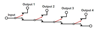
 - Cascade - Cascade switches can connect a single device to one of many others. Connection to one device ensures that all other connections are isolated. The disadvantage with this method is that the path length and the isolation specification vary with switch position resulting in variable insertion loss and screening depending on which path is in use.
- Multiplexer – Also known as a MUX, a single channel multiplexer allows one instrument to be connected to any selection (channels) of other instruments or test points on a DUT, one channel at a time. The channel may have multiple poles. This could connect a 4-wire DMM to make multiple measurements in sequence. So, for example, if you had to make 24 two-wire measurements on a DUT using the same instrument, you would have to select a 2-pole, 24 channel multiplexer.
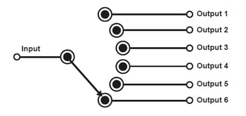
Remember when I said you could build a multiplexer using uncommitted relays, some wire, and a bunch of software coding? Well, when you buy a multiplexer from a switching vendor, most of that work is done for you! The only wiring you’ll need to do is connect the channels to various test points and the Input to the instrument being used. In the code, you simply instruct the multiplexer that you want to connect your instrument to, for example, channel 16 and the connection is made.
NOTE – At least one switching company features an option that allows the programmer to override the multiplexer functions and connect several channels simultaneously. This may be a feature that your application will need, so be sure that it is an option when you are specifying a multiplexer.
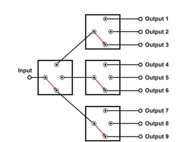
Another multiplexer type is called the Tree Multiplexer. The diagram below kind of looks like a fallen Christmas tree. 😊 Tree networks expand a switch system’s dimensions by connecting a series of switches in series. The simplest networks are based on SPDT switches which can be used to create larger multiplexers. A tree switching network can also expand the capacity of the multiplexer at the expense of more switches and greater insertion loss. In tree networks, each of the paths has the same number of switches, and to a first approximation, insertion loss will be the same for each input to output route.
Well, that’s it for today. Next, I will tackle the most complex and potentially expensive world of matrices.
For more information, check out our SwitchMate ebook and watch the on-demand webinar: Maximizing Reliability in Signal Switching to learn the importance of switching in test systems.
<< View the previous blog post in this series, "Electronic Testing 101: Switch Types and Configurations– Part 1"